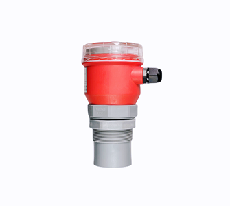
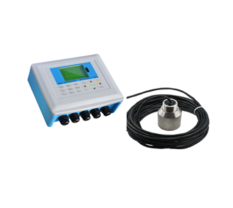
Function: split type
Protection level: IP65 for display instrument, IP68 for probe
Probe installation: according to range and probe selection
product details
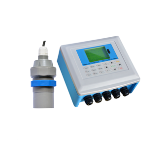
Ultrasonic underwater rangefinder
The ultrasonic underwater rangefinder produced by our company uses all Chinese menus and simple settings to meet the different needs of customers.
There are three buttons on the panel, through which the instrument can be debugged. After debugging, the measured value will be displayed on the LCD screen.


◇Enter the menu item ◇Move the cursor
◇Confirm menu item ◇Select menu item
◇Confirm parameter modification ◇Parameter modification
(1) After the indicator is powered on, press and hold the SET button (SET) for two seconds to enter the first-level menu.
For the specific menu, please see the "Menu Query Map" on the last page.
(2) Select measurement mode:
The measurement mode is divided into water depth measurement and mud level measurement. The factory default is mud level measurement.
(3) Input the height value of the probe into the "reference zero point". (The height of the probe is the distance from the bottom of the probe's emission surface)
① In the water depth measurement mode, the reference zero point setting is meaningless. For the positions of the high range point and the low range point, please refer to Figure 1.1.

Figure 1.1 Schematic diagram of water depth measurement
Range low point: the distance value from the reference plane to this position. When the low point of the range is higher than the reference plane, the value is positive, and when it is lower than the reference plane, the value is negative. The measured mud level outputs 4mA current at this set value.
Range high point: the distance value from the reference plane to this position. When the range high point is higher than the reference plane, the value is positive, and when it is lower than the reference plane, the value is negative. The measured mud level outputs 20mA current at this set value.
(4) Working with relay: enter the alarm setting option and set three parameters:
①Alarm mode: select high alarm, low alarm or close.
②Alarm value: high alarm: alarm when the water depth is higher than the alarm value
Low alarm: alarm when the water depth is lower than the alarm value
③Return difference value: The return difference value is to prevent the measurement error from causing the alarm switch to repeatedly bounce around the alarm point.
High alarm state: the alarm is released when the water depth is lower than (alarm value-return difference)
Low alarm state: the alarm is released when the water depth is higher than (alarm value + return difference value)
(5) Probe selection, parameter calibration, and algorithm selection items should be set under the guidance of professional and technical personnel.
(6) Suggestion: It is best to add an isolator in the middle when the ultrasonic underwater distance meter is connected with the interference equipment such as the motor, the frequency converter, and the PLC. If there is no direct connection, please keep a sufficient distance to reduce the electromagnetic interference of the above equipment.
Main Specifications
Function | Split type |
Measuring range | The normal range is 5 meters, 10 meters, 15 meters, 20 meters Special ranges can be customized for 30 meters, 40 meters, 50 meters, 60 meters, 70 meters and beyond |
measurement accuracy | 1%~3% |
Resolution | 5mm or 0.5% (whichever is greater) |
show | Chinese LCD |
Analog output | 4~20mA/750Ω load |
Relay Output | Single channel is 2 groups AC 250V/ 8A or DC 30V/ 5A state programmable |
powered by | Standard 220V AC+15% 50Hz Optional 24VDC 120mA Customized 12VDC or battery power supply |
Ambient temperature | Display instrument -20~+60℃, Probe -20~+80℃ |
Communication | Optional 485, 232 communication (manufacturer agreement) |
Protection level | Display instrument IP65, probe IP68 |
Probe cable | Up to 100 meters, standard 10 meters |
Probe installation | According to the range and probe selection |
Four, installation guide
4.1 Installation precautions
1. When selecting the installation location of the sensor, the following standards need to be followed:
(1) Keep the sensor perpendicular to the mud surface and the bottom of the pool.
(2) The sensor probe should be completely immersed in water and at least 50 cm away from the pool wall.
If the pool wall is uneven, or there are objects such as brackets, pipes, etc., you need to increase the distance from the pool wall to avoid the interference caused by the above objects.
(3) There should be no obstacles in the transmitting surface directly below the probe to avoid obstruction and reflection of the ultrasonic signal.
(4) The probe should be installed far away from gas bubbles and active floating solids caused by sudden changes in flow rate to ensure accurate and stable measurement.
4.2 Installation dimensions of depth sounder
⑴ The appearance drawing of the display instrument of this series of split ultrasonic underwater rangefinder:

(2) Dimension drawing of the probe of this series of split ultrasonic underwater rangefinder

4.3 Electrical wiring diagram
(1) Electrical connection diagram of single-channel ultrasonic underwater rangefinder:

◆Schematic diagram of underwater rangefinder wiring terminal

Applications:
Mainly used in sewage plants, water plants, mines, water conservancy, power plants, chemical plants, steel plants, smart water projects, various monitoring projects of geological disasters, municipal projects, sponge city projects, urban inland river governance projects, hydrology, water conservancy informatization construction Projects and other industries, scientific and reasonable management system and sound quality control system, realize product traceability management, help product safe and efficient operation, won the China National Chemical Corporation, Harbin Institute of Technology, Baosteel Group, China State Construction Group, COFCO, The trust of representative users in the industry, such as Hengan Group, has accumulated rich experience in on-site disposal of instrument products in various fields.
Integrated ultrasonic level meter
Split ultrasonic open channel flowmeter
Ultrasonic sludge interface instrument

TOP