Function: split type
Protection level: IP67 (the host can not be soaked in water) battery connection cable 0.5 meters, IP68 waterproof connector
Installation: Wall-mounted movable bracket installation
product details
1. Product introduction
1.1 HFT series municipal pipe network pressure type well level gauge is a contact type, easy to install and maintain level measuring instrument. It can meet the water level measurement requirements of most municipal pipeline network observation wells without contacting the medium. It is a new generation of wireless well water level gauge with completely independent property rights developed by our company after years of hard work.
Model: HFTF-
The pressure-type well water level gauge was designed and developed after more than 2 years in accordance with the needs of the digital network of the municipal municipal pipe network, combined with the actual situation of my country’s domestic municipal pipe network well surveying.
1.2 Battery life: The standard battery is 12VDC 24AH, which is collected every 15 minutes and uploaded every 90 minutes, which can be used for 5 months.
If the collection frequency increases and the number of uploads increases, the battery life will be shortened. All internal batteries are rechargeable. When replacing, you need to pay attention to unscrewing the fixing screws before you can replace them.
1.3 Working process
The well level gauge is divided into three working states: normal water level state, early warning water level state, and alarm water level state. A manhole with a depth of 5 meters can be set as follows: the water level below 3 meters is the normal water level state, the start of 3.01 meters is the warning water level state, and the start of 4.01 meters is the alarm water level state.
1. Normal water level status: collect once in 15 minutes and upload once in 90 minutes.
2. Early warning water level status: collect once in 5 minutes and upload once in 5 minutes.
3. Alarm water level status: collect once in 1 minute, upload once in 1 minute
This time can be manually modified and is not fixed.
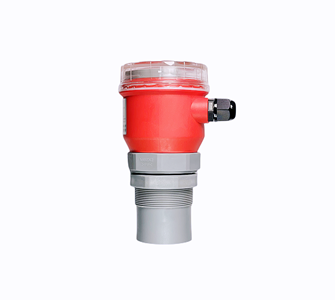
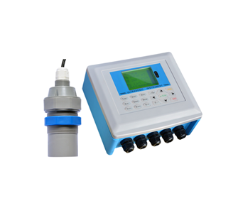
1. Product appearance
Reminder: As the product is constantly being upgraded, there will be no notice if the appearance changes.

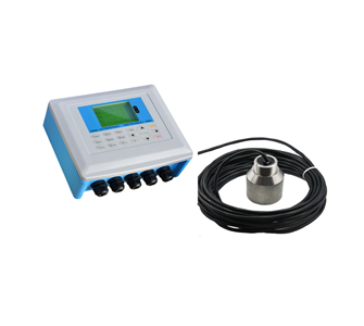
Figure 2.1.1 Top view of the host

Figure 2.1.2 Sensor diagram
2. Product external interface description

Figure 2.2.1 Battery box wiring port
Instructions for use: This interface has a root cable connected to the host to provide power to the host. The power supply voltage is 12VDC.

Figure 2.2.2 Host wiring-antenna interface and power input
Instructions for use: The antenna port is the outlet of the mobile phone antenna, and the power input port is connected to the battery box.

Figure 2.2.3 Mainframe wiring No. 1 water level gauge, No. 2 water level gauge, warning water level and alarm water level detection line
Instructions for use: No. 1 water level gauge is the water level gauge with the long cable; No. 2 water level gauge is the water level gauge with the short cable; the early warning water level and the alarm water level detection line are used to measure the early warning water level and the alarm water level.

Figure 2.2.4 Early warning water level line and alarm water level line
Instructions for use: In a manhole, if the depth is 5 meters, generally set the water level below 3 meters as the normal water level, 3 meters to 4 meters as the early warning water level, and above 4 meters as the alarm water level. Then the first step is to hang the black "alarm common line" to a height of 2.90-2.95 meters, the second step is to hang the yellow and green "alarm water level line" to a height of 3.00 meters, and the third step is to set the brown " The "alarm water level line" is placed at a height of 4.00 meters. The remaining lines do not work.
3. Main technical indicators
3.1 Introduction
Function | Split type |
Range | 5 meters, 10 meters, larger range can be customized. |
measurement accuracy | 1.0%-3.0% |
Resolution | 5mm or 0.5% (whichever is greater) |
show | No display |
transmission | GPRS wireless |
powered by | Battery powered, 12VDC, 24AH |
Battery working time | 5 months under standard working conditions |
Ambient temperature | -20 ~+60℃, |
Communication | Optional 485, 232 communication (manufacturer agreement) |
Protection level | IP67 (Do not soak the host in water) |
Main unit and battery connection cable | 0.5 meters, IP68 waterproof connector. |
Host installation | Wall-mounted movable bracket installation |
Battery installation | Wall-mounted movable bracket installation |
Power consumption | The peak power consumption of the water level gauge is 0.15W-0.30W The peak power consumption of GPRS wireless transmission is 2.4W-3.6W |
3.4 Technical parameters
Wireless transmission part | |
Channel | CLASS 10 |
Coding scheme | CS1~CS4 |
specifications | SMG31bis |
Antenna interface | 50 Ω standard SMA female |
SIM card | 3V / 1.8V |
Data acquisition part (here refers to the acquisition of the circuit) | |
input signal | 485 232、TTL |
Resolution | 16 bits |
Measurement accuracy (here refers to the collection of the circuit) | 0.5% |
Power supply part | |
Voltage | 12V |
Battery | 12VDC 24AH |
GPRS wireless data transmission and acquisition card power consumption | |
Sleep current | ≤ 5mA |
Current during upload | ≤ 300mA |
Water level meter power consumption | |
Sleep current | ≤1mA |
Working current | ≤30mA |
Pressure water level gauge | |
Precision | 1.0%-3.0% |
Supply voltage | 12V |
Other parameters | |
External dimensions of the host | 25x20x10cm (without antenna, connector, water level gauge) |
Host weight | ≤2.5KG (excluding antenna, connector, water level gauge) |
Working temperature: | -20 ~+60ºC |
storage temperature | -40 +85ºC |
waterproof level | IP68 (The external joints of the recorder housing need to be sealed by glue) |
Four, installation guide
4.1 Installation precautions
Sensor 01.1 should be placed under the water. If the cable has excess length, it should be wound on the "spool" of the mounting bracket. The No. 2 sensor should be suspended in the manhole.
If there is silt at the bottom of the rain well, do not put the No. 1 sensor at the bottom when it is lowered to reduce the influence of the silt on the measurement after the sedimentation.

Figure 4.1.1 Installation diagram
Five, wireless transmission and background server software
5.1.1 Basic precautions for wireless transmission
The pressure-type well level gauge uses mobile phone traffic to send data to the background. Generally use mobile phone cards of China Mobile or China Unicom, mobile phone cards of China Telecom are not supported. If you are working continuously for 24 hours, upload data every minute, and the monthly traffic is required to be between 50-100M. The mobile phone signal on site must be good.
5.1.2 Server configuration requirements:
1. The operating system of the server is Windows XP SP3 or Windows 7 32-bit version.
2. Server hardware requirements: CPU is Intel or AMD dual-core 2GHz or more, total memory 4GB (at least 1GB memory remaining), hard disk at least two partitions (remaining space of each partition is more than 20GB), display is a minimum of 17-inch LCD (resolution 1024 ×768 80Hz).
3. At the site installation, the mobile phone signal of China Unicom or China Mobile is good, and there is no electromagnetic interference.
4. The server has a fixed IP address (regardless of telecommunications, China Unicom, mobile broadband): this is the most ideal situation, the data sent on site can be displayed on the server software the fastest, requiring a bandwidth of 4M or more.
If the server does not have a fixed IP address: the requirement is telecommunications broadband, ADSL dial-up Internet access, bandwidth above 4M, install the paid version of Peanut Shell software, can also display the data sent back on site, the speed of receiving on-site upload data will be slower than the fixed IP address .
5.1.3 Server Software
The server software can receive the water level information sent from the scene, display it on the screen and save it.

Figure 5.1.3.1 The water level data of the ultrasonic well surveying liquid level gauge

Figure 5.1.3.2 Water level data of the pressure type well level gauge
Applications:
Mainly used in sewage plants, water plants, mines, water conservancy, power plants, chemical plants, steel plants, smart water projects, various monitoring projects of geological disasters, municipal projects, sponge city projects, urban inland river governance projects, hydrology, water conservancy informatization construction Projects and other industries, scientific and reasonable management system and sound quality control system, realize product traceability management, help product safe and efficient operation, won the China National Chemical Corporation, Harbin Institute of Technology, Baosteel Group, China State Construction Group, COFCO, The trust of representative users in the industry, such as Hengan Group, has accumulated rich experience in on-site disposal of instrument products in various fields.
Integrated ultrasonic level meter
Split ultrasonic open channel flowmeter
Ultrasonic sludge interface instrument

TOP